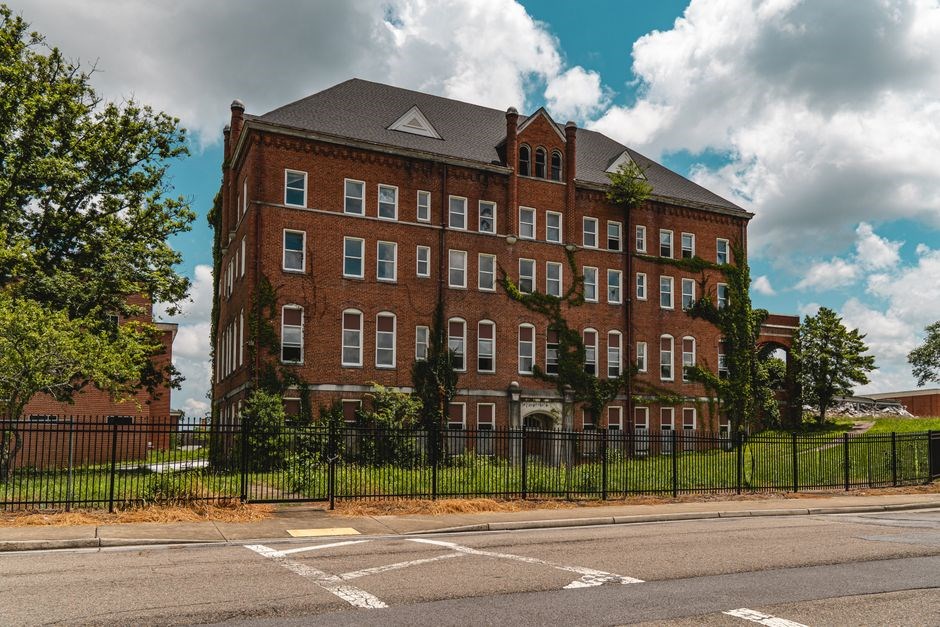
Overview of Shelby County Instructional Services Center – a regional hub for educational support
The Shelby County Instructional Services Center serves as a pivotal regional hub, offering comprehensive educational support to local schools. Through collaborative programs, it enhances curriculum delivery, provides professional development, and ensures equitable resources for all learners. It enhances equity
Mission & Services – outlining the center’s educational goals and offerings
The center’s mission is to empower educators and students through innovative instruction, inclusive practices, and data-driven decisions. Services include curriculum support, professional learning communities, technology integration, and targeted interventions for academic excellence fostering collaboration now
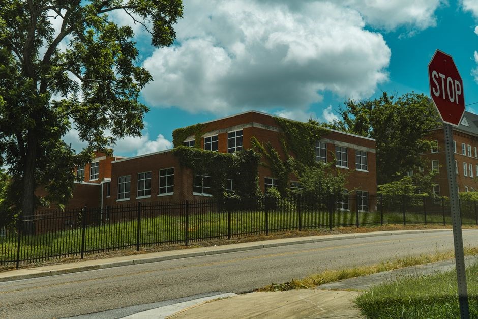
Special Education Programs – tailored instruction for students with disabilities
The Shelby County Instructional Services Center delivers a full spectrum of special education services, ensuring that every student with a disability receives support. Through collaborative IEP teams—comprising teachers, parents, and specialists—the center designs personalized learning pathways that target academic, social, and behavioral objectives. Certified professionals provide speech and language therapy, occupational and physical therapy, and counseling, all within advanced facilities. Curriculum specialists adapt core content using universal design for learning (UDL) principles, supplying assistive technology such as screen readers, adaptive keyboards, and communication devices. Ongoing progress monitoring and data analysis guide instructional adjustments, keeping each student’s growth on track. The center also hosts workshops for educators on strategies, legal compliance, and differentiated instruction. Parent support groups and transition planning prepare students for vocational training, higher education, or integration. By fostering a collaborative ecosystem, the center empowers students with disabilities to achieve academic success and growth, reinforcing the county’s commitment to education for all learners.
Specialized programs target autism spectrum disorder, intellectual disabilities, and emotional/behavioral disorders. Evidence‑based interventions such as Applied Behavior Analysis (ABA) and Positive Behavioral Interventions and Supports (PBIS) address challenging behaviors while promoting academic engagement. The technology lab offers tablet‑based tools and adaptive software, enabling full participation in digital coursework. Biweekly planning sessions keep instructional strategies aligned with evolving needs. A data dashboard tracks IEP milestones, allowing proactive adjustments. Partnerships with local universities bring research‑informed practices and internship opportunities for graduate students in special education, enriching services and exposing students to new methodologies. The center’s commitment to improvement is reflected in reviews of program effectiveness, based on student outcomes, parent feedback, and educator input.
Gifted & Talented Programs – enrichment for high‑achieving learners
The Shelby County Instructional Services Center identifies gifted learners through teacher nominations, standardized tests, and portfolio reviews, ensuring a holistic view of each student’s strengths. Once identified, students access a curriculum courses and competitions like the National Science Bowl and American Mathematics Competitions. The center partners with local universities to provide mentorship, access, and research internships, allowing students to apply knowledge in settings in real‑world contexts!!
Enrichment opportunities – dual‑credit courses, advanced placement workshops, and state‑wide competitions
Enrichment opportunities include courses, workshops, and competitions like the National Science Bowl and American Mathematics Competitions. The center partners with local universities to provide mentorship, access, and research internships, allowing students to apply knowledge in settings real‑world contexts!!
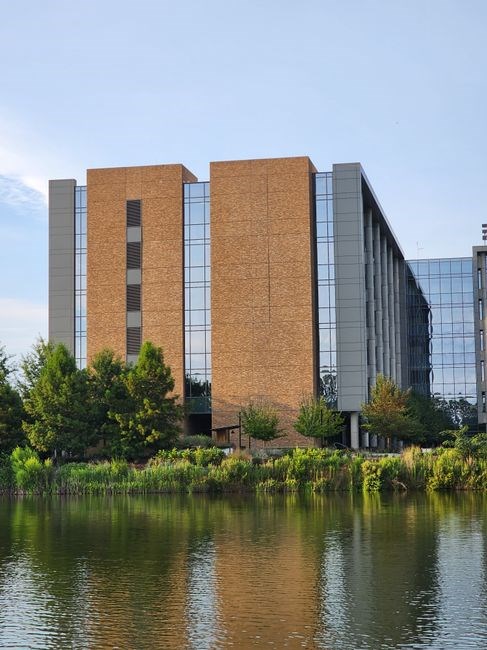
Technology labs – 3D printers, coding stations, and virtual reality headsets
Technology labs include 3D printers, coding stations, and virtual reality headsets that foster creativity and problem‑solving skills. Students collaborate on STEM projects in innovative projects and receive mentorship from industry partners, ensuring hands‑on learning that translates to real‑world applications!!
Professional development and parent engagement – workshops and counseling

Professional development focuses on differentiated instruction formative assessment tools. Parent engagement is strengthened through workshops covering enrichment strategies, college readiness, and development. The program also offers counseling and peer‑mentoring to support social‑emotional growth and well‑being!!
Staff and leadership – seasoned educators, specialists, and administrators
Staff and leadership include educators, instructional specialists, administrators who guide the center’s vision. The Executive Director steers strategic direction, while Program Coordinators manage initiatives, ensuring alignment with state standards and community needs. Their collaborative culture fosters innovation and continuous improvement!!
Curriculum Development – resources and guidance for teachers
The Shelby County Instructional Services Center’s Curriculum Development team delivers a comprehensive suite of resources, lesson plans, assessment tools, and digital repositories that align state standards with district priorities. Each packet contains clear objectives, differentiated strategies, formative rubrics, and data dashboards for real‑time progress monitoring. Teachers access searchable libraries of best‑practice exemplars, peer‑reviewed research, and instructional videos, enabling customization for diverse learners. Professional development workshops—both in‑person and virtual—focus on backward design, project‑based learning, culturally responsive pedagogy, and technology integration. Experienced specialists lead sessions, provide coaching, and facilitate peer‑review circles. Assessment alignment is central: the team collaborates with specialists to create formative and summative rubrics that reflect learning goals, provide transparent feedback, and inform data‑driven instruction. Follow‑up coaching supports continuous improvement, ensuring resources remain current, evidence‑based, and aligned with evolving standards. The center also offers a digital library of interactive simulations, adaptive learning platforms, and a mentorship program that pairs teachers with experienced educators to refine instructional strategies. Additionally, the team curates a repository of research‑based best practices and organizes quarterly webinars to share emerging trends and evidence‑based innovations, ensuring that curriculum remains dynamic and responsive to student needs!!!
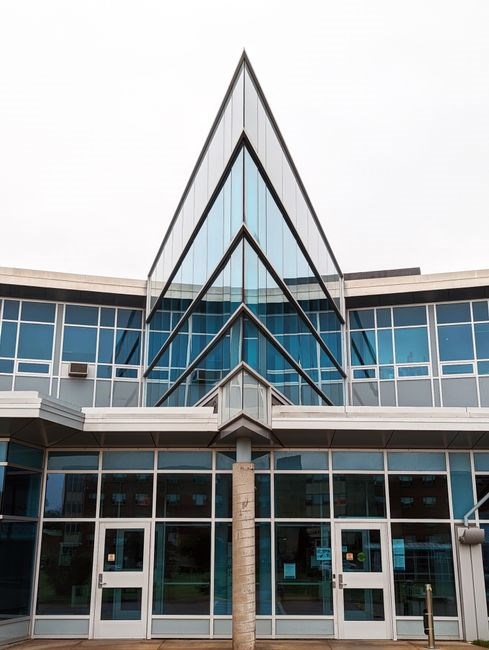
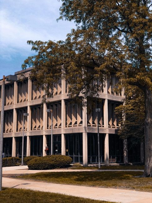
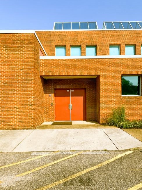
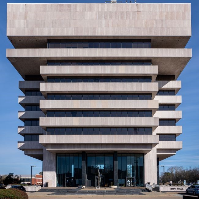
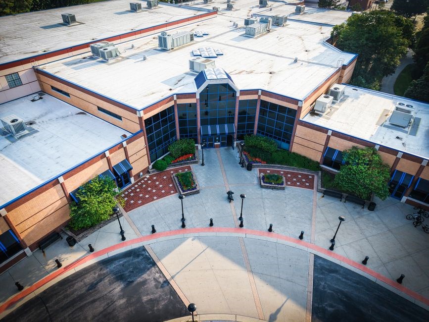
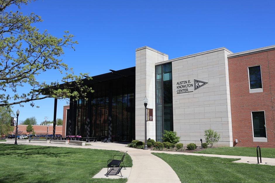
Facilities & Resources – modern classrooms, technology labs, and learning materials
The Shelby County Instructional Services Center boasts state‑of‑the‑art facilities designed to foster innovative learning. The main wing houses ten fully equipped classrooms, each with interactive whiteboards, high‑speed Wi‑Fi, and ergonomic furniture that supports varied teaching styles. Adjacent, a technology lab features 40 laptops, 12 3‑D printers, and a robotics suite that lets students design, prototype, and test STEM projects. The media hub includes a 4K video production studio, a sound‑proof recording booth, and editing suites for educators to create multimedia lesson plans. A collaborative commons offers flexible seating, modular tables, and a digital library of e‑books, open‑access journals, and curriculum resources. For hands‑on science, a laboratory provides microscopes, chemical kits, and safety equipment, while a makerspace supplies craft supplies, woodworking tools, and digital fabrication tools. The resource library houses over 5,000 instructional materials, including differentiated lesson plans, assessment rubrics, and professional development modules; All spaces are accessible, climate‑controlled, and designed for students with diverse needs. Sustainability features—solar panels, rainwater harvesting, and energy‑efficient HVAC—show the center’s commitment to environmental stewardship. Regular tours and open‑house events invite teachers, parents, and community partners to experience the resources and collaborate on future initiatives. The center’s professional development suite includes a 20‑seat lecture hall, a simulation room for virtual field trips, and a quiet reflection area with mindfulness resources. By integrating technology, hands‑on learning, and collaborative spaces, the Shelby County Instructional Services Center exemplifies a modern educational ecosystem that supports teachers, students, and the broader community. The center also offers a dedicated arts studio, a green‑roof garden, and a flexible makerspace that encourages creative exploration across disciplines. All in all, the center is a beacon of educational innovation and community growth now!
Staff & Leadership – experienced educators and administrative personnel
The center’s leadership team blends seasoned educators with strategic administrators. The executive director, a veteran instructional specialist, guides vision, while program coordinators—each with advanced degrees—manage curriculum, tech, and special services. Together, they foster growth and inspire learning now.
Executive Director – overseeing strategic direction
At the helm of the Shelby County Instructional Services Center is the Executive Director, a seasoned educational leader with a track record spanning over two decades. Holding a doctorate in Educational Leadership and a master’s in Curriculum Development, the director brings a blend of research acumen and classroom experience. Prior to joining the center, this individual served as a district superintendent, where they spearheaded initiatives that increased student achievement by 12% statewide. Their strategic vision focuses on data‑driven decision making, equitable resource distribution, and fostering a culture of continuous improvement. Under their guidance, the center has launched a district‑wide professional learning community that connects teachers across schools, providing collaborative workshops and coaching that align with state standards. The director also champions technology integration, ensuring that every classroom is equipped with up-to-date digital tools and that staff receive ongoing training in blended learning models. In partnership with local higher‑education institutions, they oversee research projects that evaluate instructional practices and translate findings into actionable policy. Their leadership style emphasizes transparency, stakeholder engagement, and a commitment to student‑centered outcomes. The Executive Director’s role is pivotal in aligning the center’s mission with the educational goals of Shelby County, ensuring that every student has access to high‑quality instruction and support services.
Program Coordinators – managing specific instructional initiatives
Program Coordinators at the Shelby County Instructional Services Center are the linchpins of targeted educational interventions. Each coordinator specializes in a distinct instructional domain—special education, gifted and talented, literacy, STEM enrichment, and digital learning—ensuring that every initiative receives focused expertise. Their responsibilities encompass curriculum design, resource allocation, and fidelity monitoring across the county’s 18 public schools. Program Coordinators conduct assessments, gathering data from classroom observations, student performance metrics and teacher feedback to identify gaps and opportunities. They translate insights into actionable plans, collaborating with administrators to embed best practices into daily instruction. Professional development is a core component of their role; they organize workshops, webinars, peer learning circles that empower teachers to implement evidence‑based strategies. Additionally, coordinators maintain partnerships with local universities, securing research grants that fund pilot programs and longitudinal studies. They serve as liaisons between the center and external stakeholders, ensuring community resources are integrated into the educational ecosystem. By tracking implementation outcomes, they refine program components, fostering a cycle of continuous improvement. Their leadership fosters a culture of collaboration, data‑driven decision making, and a shared commitment to elevating student achievement across Shelby County.
Partnerships – collaborations with schools, colleges, and community groups
The center partners with local high schools, community colleges, and nonprofit groups to co‑develop curricula, share tech, and host joint workshops. These alliances expand access to courses, mentorship, and learning for students.
The Shelby County Instructional Services Center collaborates closely with surrounding school districts to implement joint professional development initiatives and curriculum alignment projects. Through a structured partnership model, the center offers district-wide teacher training workshops focused on differentiated instruction, data‑driven decision making, and inclusive classroom practices. These workshops are delivered by certified specialists and experienced educators, ensuring that instructional strategies are both research‑based and contextually relevant. Additionally, the center coordinates district‑level mentorship programs, pairing veteran teachers with new hires to foster continuous learning and peer support. Joint grant applications enable districts to secure funding for classroom technology upgrades, STEM enrichment kits, and specialized learning materials. The center’s collaborative framework also includes shared assessment tools, enabling districts to benchmark student progress across schools and identify areas for targeted intervention. By aligning professional learning communities across the region, the center promotes a culture of collective responsibility for student achievement, providing scalable solutions that can be adapted to each district’s unique needs. This partnership model has led to measurable improvements in teacher confidence, instructional quality, and student outcomes, reinforcing the center’s role as a catalyst for educational excellence in Shelby County. These efforts also boost community engagement and student well‑being!!!!
Higher Education – partnership with local universities for research and services
The Shelby County Instructional Services Center has forged a robust alliance with nearby higher‑education institutions, creating a dynamic conduit for research, innovation, and professional services that directly benefit K‑12 educators and students. This partnership leverages university faculty expertise in curriculum design, assessment science, and educational technology to co‑develop evidence‑based instructional modules that are immediately deployable across the county’s schools. Joint research initiatives focus on longitudinal studies of student engagement, the efficacy of adaptive learning platforms, and the impact of culturally responsive pedagogy, providing data that informs policy decisions and instructional practices. The center also hosts a semester‑long internship program, allowing university students in education majors to gain hands‑on experience in classroom support, data analysis, and program evaluation while contributing fresh perspectives to ongoing projects. These workshops are delivered by professors and students, ensuring participants receive cutting‑edge content grounded in scholarship. Learning boost. The partnership further supports a shared resource repository, where digital libraries, instructional videos, and research articles are curated and made accessible to all district staff. By combining the research rigor of academia with the practical needs of local schools, the Shelby County Instructional Services Center fosters a culture of continuous improvement and evidence‑based practice that elevates educational outcomes across the region.
Funding – state allocations, grants, and community contributions
The Shelby County Instructional Services Center sustains operations through a diversified funding portfolio blending state appropriations, competitive grants, and local community support. State allocations, derived from the Kentucky Department of Education’s equitable distribution formula, provide a foundational budget covering core instructional services, professional development, and essential technology upgrades. These funds are earmarked for program continuity and are reviewed annually to align with evolving educational priorities.
In addition to state support, the center pursues federal and private grants targeting initiatives like STEM enrichment, inclusive education, and digital learning. Recent awardees include a National Science Foundation grant that funded a district‑wide maker‑lab initiative and a Department of Education grant that expanded the center’s data analytics capabilities. These grants supplement operational costs and allow the center to pilot innovative instructional models across the county.
Community contributions sustain programs. Local businesses, foundations, and volunteers donate in‑kind items, sponsorships, and fundraisers supporting equipment, field trips, and enrichment activities. The center’s “Community Partners” program invites stakeholders to co‑design projects, ensuring funding meets the needs of each school district. This collaborative approach fosters ownership and strengthens the center’s capacity to respond swiftly to emerging challenges!!!